
About a year ago I made 3 videos about Open.HD and they are still sat there on YouTube if you’d like to take a look. in the first video, I talk about what Open.HD is and what sort of equipment we’ll need to get the system set up.
In the next video, I connected everything up on the bench. Going from the simple “can the ground station see the air Pi”, and then connecting up telemetry from an iNav based flight controller and then connecting a radio via USB and sending the control signal over the link.
Then in part 3, I put the system together in an iNav Rover build and drove it around a park using the Pi ground station to send the command signal and receiving the telemetry.
Problems with this Build / Video
Although everything broadly worked in this last video, there were a few issues. Firstly I was using the official 7″ Pi touchscreen – it’s a great little screen, but out in the sun and it might as well be a mirror so I really couldn’t see what was going on. I used an app called QOpenHD on my iPhone. The idea being that it could connect to the ad-hoc wifi network that the ground Pi created and also show the picture, so I used this to screen record. Bu the problem here was that the iPhone dropped lots of frames, sometimes freezing up for 10 seconds or more whilst the 7″ display was fine. So you, as the audience don’t get to see what the quality of the video was really like, and nor do I because the screen was acting as a mirror.
There was also an iNav bug that I wasn’t aware of, the MAVlink telemetry packets weren’t quite correct, and so the compass kept telling me it was always heading north. That’s not great if you ever want to use RTH or any sort of navigation mode. There was actually a workaround that you could enable in the code, but I didn’t know that at the time.
New Beginnings
That brings us up to now – I had been planning to get on and do some more on Open.HD, but between lockdown and the various problems I’ve had with my knee which restricted mobility, it kept getting put on the backburner… until now. Back when I did those videos, I was using iNav 2.5.2 and Open.HD 2 release candidate 17. Since that time, iNav has moved into a major release, v3 (the current one at the time of writing is 3.0.1) and Open.HD finally got its 2.0 release, and is now on 2.0.8. Given these new releases, and the fact I’ve forgotten most of what I did before, I thought the useful thing would be to start all over again.
So what this document aims to do is go into a little more step-by-step detail in the setup, both on the Pi side of things and the iNav side. Initially, I’ll be redoing the Rover build, but working on a different way of getting myself and you, the viewer, a better way of being able to see what’s going on. Let’s crack on.
The Equipment: What I’m using
I’m going to be using a fairly minimal setup and design around the easiest way of putting things together. At the heart of this system, you will need two Raspberry Pi’s. I’m going to use a Pi 4 for my ground station, and a Pi Zero for my “Air” Pi (although for this build, it won’t be flying)
There doesn’t seem to be any particular advantage in using a more powerful Pi 4 in the “air”. The great thing about Pi Zero’s is that they are very cheap (just as well as I managed to misconfigure the GPIO pins in one of my Zero’s and broke it) and they are much smaller than the Pi 4 and use less power.
The expensive part of the system is probably the USB wifi adapters, and you’ll need two of them. Not all wifi cards are supported, just certain chipsets. You can get some cheaper ones at the likes of Aliexpress, but I used 2 of the recommended ASUS AC56 dongles.
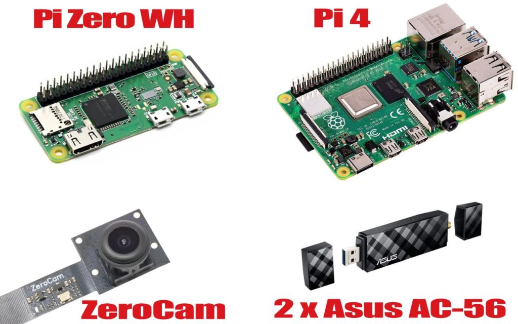
The Pi cameras aren’t particularly great, they remind me of FPV cameras from at least 5 years ago – mostly in the fact that they seem to lack any wide dynamic range, but it’s a simpler config to use them, so I bought the ZeroCam FishEye (for a wider FOV). You will also need a few micro SD cards to run the OS and Open.HD and something to display your image from the ground station. As mentioned before, I’d bought the 7″ touch screen, but I’m not sure if this will be used in this version yet.
Over on the Rover side of things, well you’ll need something to act as a rover. I’m using an old Tamiya RC car with lots of stuff stripped out. As long as there’s a control signal for throttle and steering, then we should be good for starters. We will need a flight controller of some sort to provide a telemetry signal to pass back to the ground station. I had a space HGLRC Zeus F722 and you will need a combination GPS/Compass for a rover – a GPS on its own is not enough. I’m using an HGLRC M81.
Downloading / Installing Open.HD
First off, I went over to the Open.HD releases page on Github to download the latest release. Interestingly (although this will obviously change) the 2.0.8 version says it’s like the last v2 release before v3 which will be coming “in a few weeks”. That was 6 months ago – I think Open.HD may have had a shuffle of people leaving/coming into the project that’s delayed this. No matter, I downloaded the 2.0.8 Buster image. IMPORTANT: it’s easy to cruise down to the bottom of the release and assume you want the zip file, you don’t. You want an image ready to flash onto an SD card which is closer to the top of the page. I got the 2.0.8 one here.
You can’t simply copy this file to the SD card and use it in the Pi, this image needs to be written in a certain way, and for that, you’ll need another piece of software. For me, running on macOS I use a program called ApplePi Baker. Windows owners have a whole host of possibilities, but Open.HD recommends Etcher. The process is similar on all image writers, you select your destination (SD card) and your source image – the tar.gz file you’d downloaded. Don’t forget that you’ll need to do this write twice: Once for the ground Pi’s SD card and once for the Air Pi’s SD card.
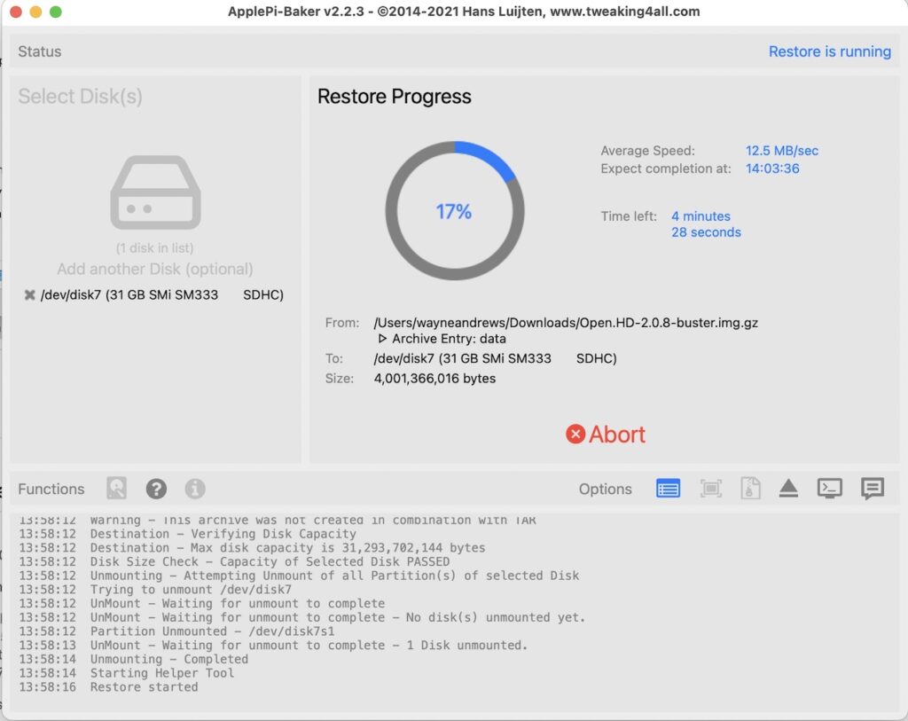
At this point, you can pop the SD card in your ground station and try booting it up, but plug in the wifi dongle as well as it doesn’t bother booting all the way without it. That should all work fine, but at this stage, you’ll probably want to configure a few things – certainly, in the case of my 7″ touch screen, the display renders upside down so I need to change that. There are two ways of messing with the config files. I would split that up by saying if you are comfortable with the Linux command line then the ssh way is probably for you, for everyone else the SD card in your computer will show you the boot partition and allow you to edit files using in the config directly. Make your changes here and then pop it back in the Pi and boot up again.
If you want to use ssh it’s pretty easy. Once the Pi boots up to the OSD screen, but default it’ll make an ad-hoc wifi network with the SSID of Open.HD and a default password of wifiopenhd your Pi should come up with an ip address of 192.168.2.1 and so you can ssh to it directly with ssh pi@192.168.2.1
One thing that surprised me on testing the since last time, is a bug in which running sudo su - wouldn’t find the right path for the rw script (to make the filesystem read/write) wasn’t fixed and thus I also ran a sudo -s before cd’ing into the /boot directory.
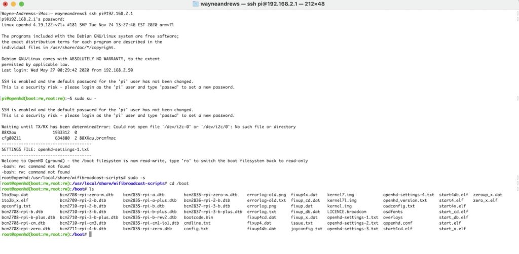
From this point forward I’ll just talk about the edits I make, you could either do this with an editor with the SD card plugged into your PC or via an ssh command into the running Pi system, it won’t matter, but don’t forget to reboot the Pi after reconfiguring if you are using ssh.
There are two files that you might need to edit (depending on your setup) they are config.txt and openhd-settings1.txt (there are other openhd-settings files and are for managing different configs, but we’ll just concern ourselves with 1 for now) Given that my 7″ touch screen rendered things upside down, I added a single line to the config.txt file of –
lcd_rotate=2Most of the important settings in the openhd-settings1.txt file are listed here
# >>>>>>>>>>[RC JOYSTICK MODE OVER OPEN.HD SETTINGS]
# Set this to "mavlink" to enable R/C over Open.HD using mavlink protocol or "msp" for MSP
# protocol.
# Set to "sumd" for Graupner SUMD, "ibus" for Flysky IBUS, "srxl" for Multiplex SRXL/XBUS
# Mode B. Set to "disabled" to disable
# **See joyconfig.txt for other settings, default settings work for Taranis in USB.
RC=mavlink

# >>>>>>>>>>[DEDICATED WIFI-CARD UPLINK/RC MAC ADDR.]-- If different types of Ground wifi cards are used.
# Set this if you have 1 High-Power ground card plus 1 or more lower power cards so that
# all uplink is sent using the high-power card. Otherwise, leave "0" and RC/Uplink will
# be automatically selected based on RSSI signal.
# ***Also Set for Bandwidth Switcher Function (Below)***
#Ground RX card Primary
PrimaryCardMAC=0

# >>>>>>>>>>[TELEMETRY WBC/OTHER]--
# wbc = use wifibroadcast as telemetry up/downlink
# external = use external means as telemetry up/downlink (LRS or 3DR dongles)
# if set to external, set serialport to which LRS or 3DR dongle is connected
# both on ground and air pi
TELEMETRY_TRANSMISSION=wbc

# >>>>>>>>>>[TELEMETRY UPLINK]--
# Set to "disabled" or "mavlink" for Mavlink (QGC, Missionplanner, etc.)
TELEMETRY_UPLINK=mavlink

# >>>>>>>>>>[USB OPENHD-RC SERIAL PORT/BAUDRATE]--Serial Port Settings between Air Pi & Flight Controller.
# Serial port and baudrate (19200 is minimum)
# Set this to "/dev/serial0" for Pi onboard UART serial port or "/dev/ttyUSB0" for FTDI adapter.
FC_RC_SERIALPORT=/dev/serial0
FC_RC_BAUDRATE=115200

# >>>>>>>>>>[OPENHD-FC SERIAL PORT/BAUDRATE]-- Air Pi and Flight Controller
# *Should be the same as FC_RC_BAUDRATE
FC_TELEMETRY_SERIALPORT=/dev/serial0
FC_TELEMETRY_BAUDRATE=115200
There are some changes to make for me based on the fact that I’m going to use iNav, but tell iNav to use Mavlink telemetry data, and also that I’m going to plug in my radio via USB to the ground Pi and send control signals over the wifi link. iNav will use a telemetry baud rate of 115200, so that’s already set by default. You might find some old APM boards use 57600 (I’ve no idea what the newer Pixhawk uses) whatever the case though, make sure that you make the same changes in your ground and air pi SD cards.
The other thing to change in order to use a USB attached radio in iNav is the line that says RC=mavlink. If you are using something that runs Ardupilot, then all good, but on iNav we can use iBus or Sumd as our control link, so I’m going to use ibus. So despite the seeming complexity of the file, I’m just having to make a single change (albeit on bath cards) which is listed below – everything else in the file remains at its default
# >>>>>>>>>>[RC JOYSTICK MODE OVER OPEN.HD SETTINGS]
# Set this to "mavlink" to enable R/C over Open.HD using mavlink protocol or "msp" for MSP
# protocol.
# Set to "sumd" for Graupner SUMD, "ibus" for Flysky IBUS, "srxl" for Multiplex SRXL/XBUS
# Mode B. Set to "disabled" to disable
# **See joyconfig.txt for other settings, default settings work for Taranis in USB.
RC=ibus
So before going any further into the Open.HD setup, let’s talk about the iNav side of things. First things first, and that’s flashing my F722 board with the latest iNav version. Before doing anything, I picked up a new version of the iNav Configurator from https://github.com/iNavFlight/inav-configurator/releases I did note that there was a sign up advising not to restore a full diff. So what I did is just make a note of the basic changes I did in order to make a new config and then set it up the same as previously. Rather than take a clip dump or anything, and knowing my setup wasn’t that complex I simply took some screenshots for my own reference. I flashed iNav 3.0.1 on my board.
Hand in hand with the iNav setup we need to talk about the physical wiring here… which I must admit is a bit of a mess as far as this rover goes. However, if we ignore all the flailing servo leads I’ve got everywhere and the two power sources we can get down to the basics. Here’s an actual top-down picture of the rover… yuk
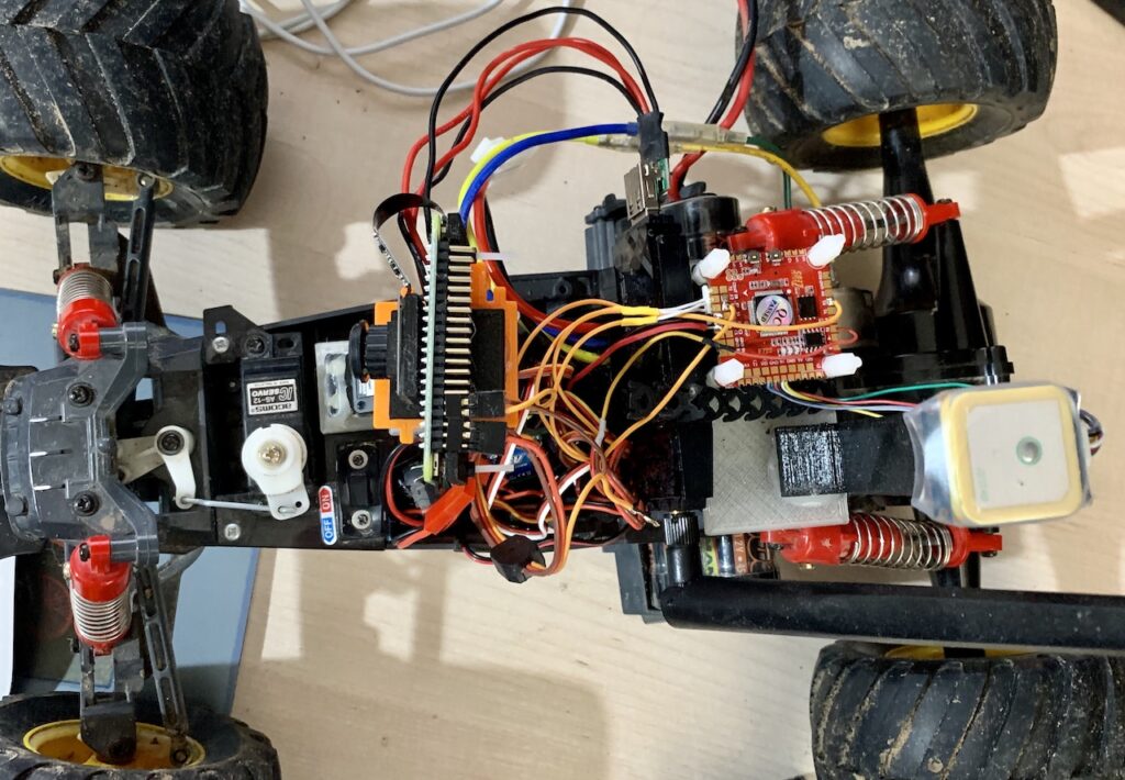
…but here’s a more friendlier representation. At least that’s what I hoped, but then I drew it and there were…. well, there are lots of lines isn’t there. There are even some I haven’t drawn in for fear of making it look even more complex. in this configuration, the 5v and GND lines to each of the servos is being supplied by the BEC, and the ESC and Motor is actually being supplied by the model’s own NiMH 6 cell pack. I’ll attempt to explain in more detail as we go.

For iNav setup, there were a few screens in the configurator which were particularly relevant to my setup. The first is the Mixer page. In the more simple setup, you’d just have a single motor and single servo (for steering) in my setup I also added a pan and tilt servos for my camera. This is 3 servos in all, but you’ll notice by mixer has been set up for 4. Why? iNav doesn’t let you assign which output you’d like which servos (or motor on) so my motor got automatically assigned to S7 and then the servos in order to S1, then S2, S3 etc. I found that I wasn’t getting any signal out of S3 (a broken FC perhaps) but S4 seemed ok. Unable to specifically move the servo to S4, I just had to leave a duplicate on S3. Hopefully, your setup will be more straightforward.

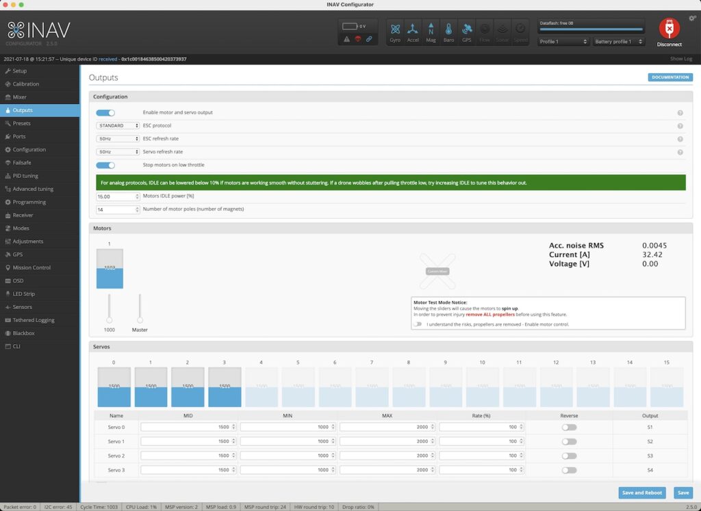
It was less of a thing to think about, but can be easy to miss. If you are making a rover build, then odds on you aren’t going to be running BLHeli_S or something on your ESC, so in the outputs tab I needed to set my ESC to standard and the rates to 50hz
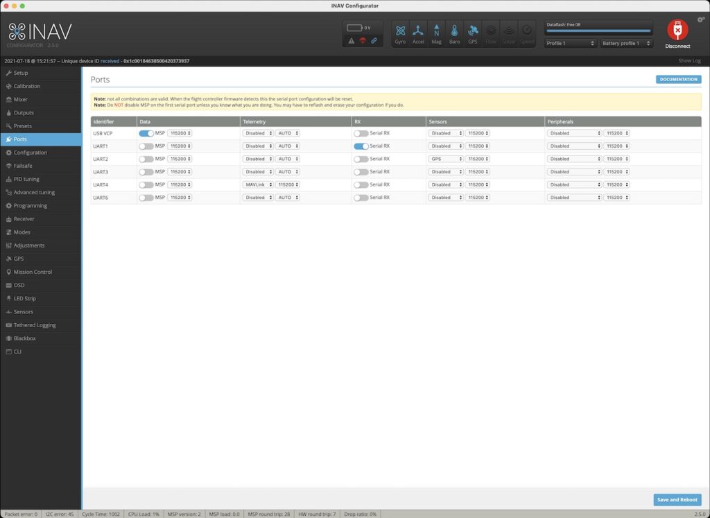
The Ports page is another important one to configure correctly. I have the GPS/Compass on UART2, and I’ve got the TX from the Pi going into UART1 to transmit the control signals, so this has serial rx enabled. I also need my telemetry output to get back to the Pi and so on UART4 I’m pushing MavLink telemetry.
The only changes in the Configuration Tab so to make sure telemetry output was on and select reversible motors mode – which is common for car ESCS, but obviously less so on quads and planes. You should ensure (if using Quad or a rover) that you have your magnetometer displayed in the sensors.

Finally, in the Receiver tab, I needed to make sure I set my receiver type to Serial and my Serial provider to ibus – just matching what I’d laid out in Open.HD
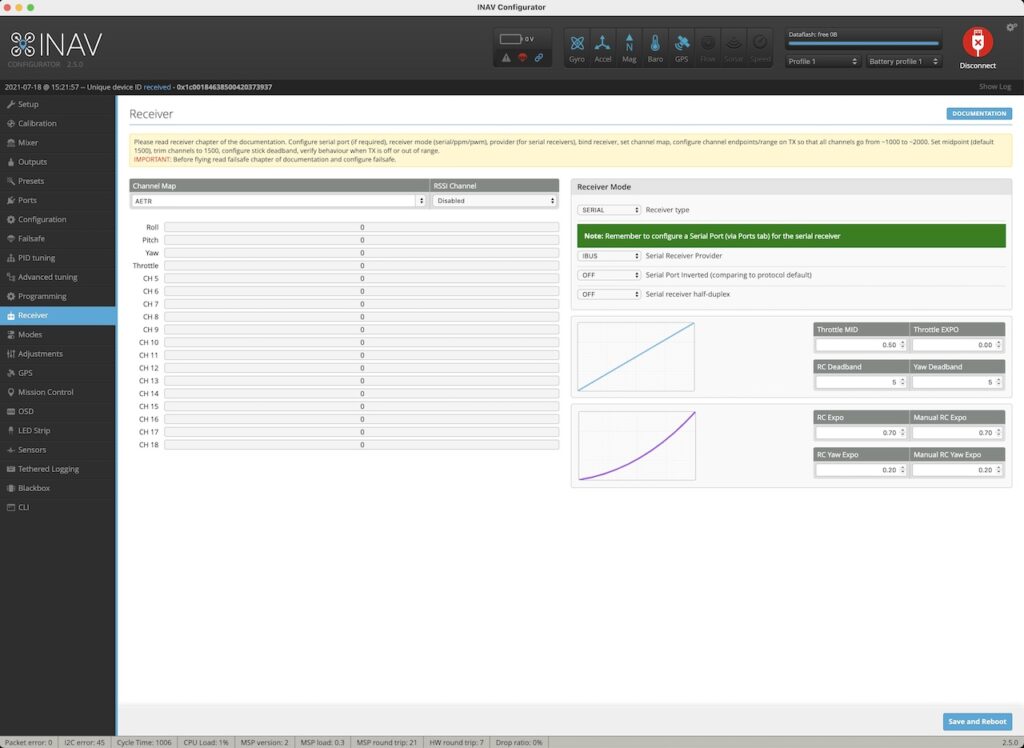
I’m missing some things out here, most crucially the modes tab – you’ll want at least an arming switch. I’ve made it default to Manual once armed at this point, I’ll come back and look at fancier modes later.
So I mentioned the physical wiring but mainly from the flight controller point of view, the wiring to the Pi Zero is also very important as well. We use just 4 wires to the Pi in this config, but it’s pretty important not to get these wrong, else the Pi Zero will blow (ask me how I know!)
Specifically, we need to power the Pi Zero via a 5V input, hence I’m taking the 5V supply from the dedicated BEC I have in the diagram to pins 4 and 6. In order to get information from the flight controller back to Open.HD we connect T4 (transmit on UART4) from the FC to pin 10 (UART0_RXD) on the Pi. Similarly to send control signals from Open.HD (although you can just as easily use a normal radio)I connected up R1 (Receive on UART1) on the FC to pin 8 (UART0_TXD) on the Pi.
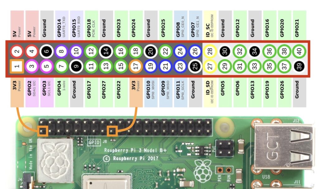
One word of warning about the Pi’s own UART: It uses 3.3v logic. I had an old APM board that I was going to use, but checking with a multimeter (check GND and TX PIN) it actually used 5v logic. Whilst you can get logic convertors for this, I checked and found this Zeus FC used 3.3v logic and so used that. But it’s worth checking your card to make sure.
This is not quite the only wiring required on the Pi Zero. I haven’t mentioned the camera connection, but it’s a very simple case of pushing the ribbon cable into the connector and then closing the tabs. More of a hassle if the connection of the USB Wifi adapter. Clearly, we can’t have it actually plugged into the USB connector, so what do we do. I came up with the following idea.
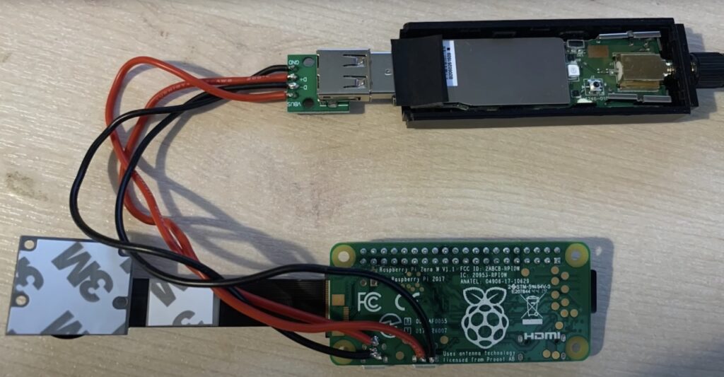
What I did was buy a USB breakout board from eBay. I got this one, but where to get them may depend on where you are in the world. The micro USB ports are a little weird on the Pi Zero, with one being used for power – the normal way of actually powering the Pi Zero, and the other one used for data. The power we’re supplying the Pi with via the GPIO pins will then supply the USB device, so all good there. Just a case of connecting up data lines to data lines and the 5V/GND lines correctly.
This puts me to where I’d got to in my previous videos and a quick test on the bench all worked as expected – so yay so far, but let’s now tackle the issue I had before – not being able to see where I was going in the 7″ touch screen.
My initial thought here was to just plug an HDMI cable into one of the HDMI outs on the Pi (the 7″ touch screen uses a DSI connection) and see what I get. Obviously, you could connect to any HDMI enabled monitor, but as I wanted to be able to record this, I plugged it into an Elgato HD60S+ – something very popular amongst Twitch streamers for capturing their game play and streaming it (although usually in conjunction with running OBS). I plugged in the HDMI and got this on the screen.
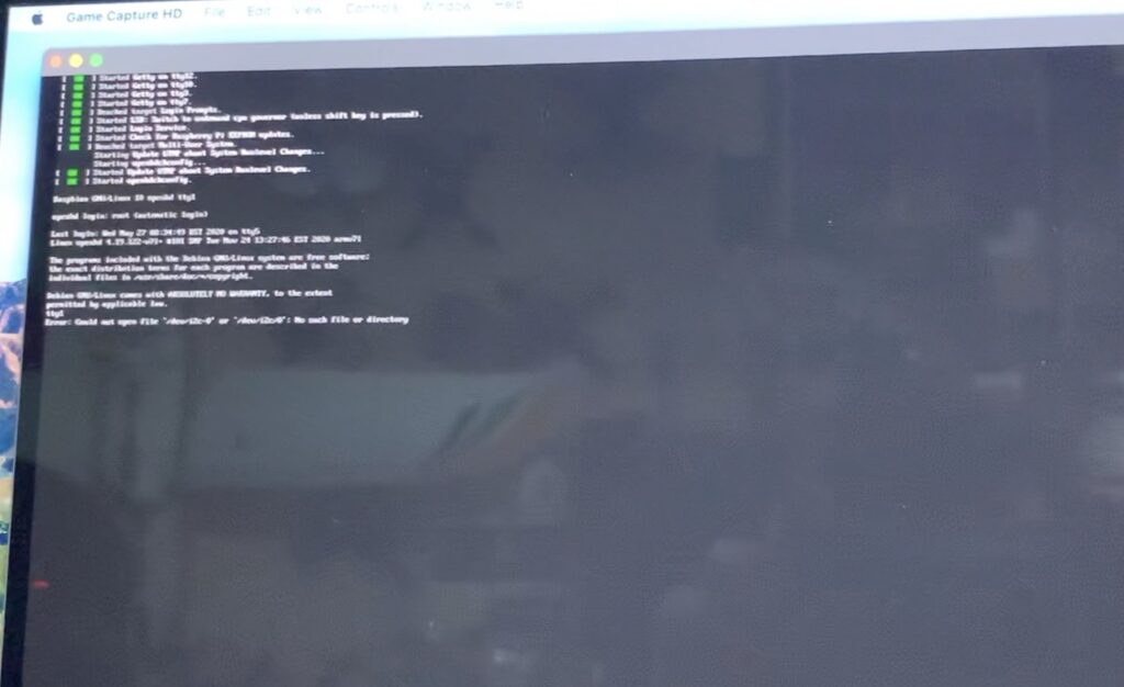
On the touch screen we got the full load of boot messages followed by the Open.HD OSD (eventually) so whilst something happens, it’s not mirroring the screen. There is an actual section of the openhd-settings-1.txt to change here. It should just be the case of uncommenting the MirrorDSI_To_HDMI=Y option.

I tried it, but I had exactly the same display on the HDMI output. I went back to the Open.HD issues page and found Issue #449 in which other people were mentioning that this doesn’t work. Ok, so looks like the touch screen isn’t going to work for me here… at least yet. In terms of fixing the problem, things are actually pretty easy – by simply removing the Pi 4 from the 7″ touch display, I should be able to connect up and HDMI cable to it and have it work. I did exactly this for a test of concept and had no issues using my Elgato to capture the output onto my computer.
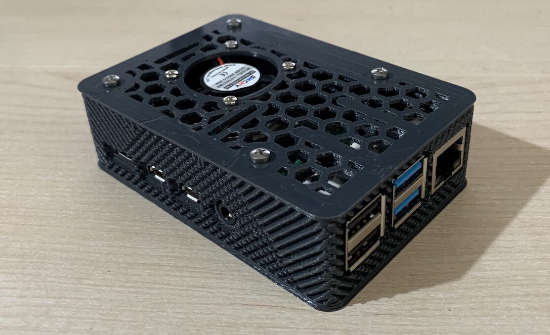
What I wouldn’t want is a bare unprotected Pi 4 at the field though. So I found a nice looking case to print from Thingiverse. What I liked about it (other than the fact that it fitted really nicely) is that it had a space to attach a small fan. Without any cooling, the Pi 4 will run very hit and can easily overheat. It came out pretty well I think.
The Elgato has two HDMI sockets, one to act as an in for it to capture the video, and another as an out where it acts as a passthrough. As there’s some latency (albeit small) between the video capture and what appears on the screen, having a through is important as that’s latency free. So I plugged the out into an old pair of goggles I reviewed way back in 2017 called the Eachine Goggle Two.
At the time of review, I thought they were ok. Way too big, compared to FatSharks, for regular FPV and they didn’t have any focus option, so people with different long/short-sightedness had issues. They did, however, have a native 1080p display and HDMI in which I wanted to use. My normal goggle is the FatShark Dominator 3 which do have HDMI in, but a native resolution of only 640×480 so seemed a bit pointless with HD.
More problems though. If I plugged the goggles in on their own then I got a picture in the goggles – yay. If I use the computer only, I got a picture, but if I used both at once – it woudn’t work. What seems to happen is the HDMI negotiation takes place between the Pi and the Elgato, and whatever they agree to the goggles don’t seem to like. I did go in and make a specific change for the Goggles Two in the config.txt and if you are using goggles – and I know there’s very little chance of anyone else also having the Goggles Two, then check this file to see if your goggles are listed as it will help you get the right settings quickly.

So now it seemed that the Elgato was also off the table. I say this, but I’m using old and strange goggles, so it’s quite possible that some more up to date (and better) goggles will work just fine in this combination. So I felt like the only option was to use QOpenHD running on my Android tablet. I knew from the previous comments that the iPhone in particular had a problem with breakup, so I though switching to Android would help. I had a test drive around the garden and it was fine, and the screen recording looked ok – but I wasn’t happy about it. I asked the members of the Open.HD telegram group id they had any experience with using Elgato in the capture.
The Open.HD Telegram group is a really useful wealth of resources and is a very active community. You get the developers and a lot of expereinced pilots in there that are regularly flying, testing etc and will try and answer questions. Of course, an expectation that you have at least read the wiki and have tried things is a reasonable expectation. In other words, you just don’t turn up and say “How do I do this”. Anyway, whilst nobody had the specific experience I’d been trying I did note that a few people remarked about the wifi hotspot causing some interference and range issues.
The wifi hotspot is exactly what we use in QOpenHD. On the tablet I’d set my wifi to the Open.HD SSID coming from the Pi and then QOpenHD would pick up the data. I didn’t like that fact I was using a wifi hotspot any longer. I messaged one of the pilots I knew had a lot of really great success and, more importantly, great DVR recordings. He told me that he used a tethered connection to his android device and so could disable the hotspot. This was essentially Ethernet over USB.
If you have an Android device it may prompt asking you what you want to do when you plug in the USB, this is usually Charge, Transfer Photos, or Transfer files. I went into the developer options of my tablet and found that I did have an option to run Ethernet over USB. Do all Android devices have it? I don’t know, but it’s certainly worth checking out. You may have to put your device into developer mode to check this. This isn’t a scary thing and you can also remove it, here’s a guide on how to turn developer mode on.

With this mode enabled, I was able to plug in a USB lead between my tablet and Pi 4, run QOpenHD and see the live picture – success!! By doing this I was also able to remove the Wifi hotspot from the Pi, which is recommended for the cleanest picture. To do this, once again edit the openhd-settings-1.txt and change the WIFI_HOTSPOT line to N

So we are ready to test, but before going further let me show you the setup of all my equipment as I did a few things to try and make powering everything easier.

I was going to try and label everything in this picture, but with all the wires crossing over, it’s tricky – so I’ll just describe things. Let’s start with the Pi 4 and branch outwards.
On the right-hand side of the Pi are it’s USB connectors. We have one connected to the radio, another connected to the Wifi adapter, and the last connected to the Android tablet. On the bottom side of the Pi the black cable is connected from the mico-HDMI on the Pi to the Mini-HDMI on the goggles (you’ll notice an adapter there – dealing with such odd HDMI connectors is interesting). The white connector on the underside of the Pi is the USB-C connector I made to supply the 5v power. Previously, I’d used a 5A BEC for this, but I decided a better thing to do was use a charger which could operate as a power supply. It’s a relatively common feature now, but not every charger will do so. The charger is getting power from a 4S 5.2A lipo which will last for hours and hours. Another handy thing the charger has is a USB socket which supplies 5v at up to 2.1A. So plugged into this is a 9v step-up convertor – it’s something actually designed to power goggles from a USB supply and was a review of some FXT products from several years ago.
The actual test of all of this is in this new video – a video which also tells you to look at this blog post, weirdly full circular 🙂
What I notice from the video are several things. Firstly, the DVR ground recording and everything else seems to work pretty well. I do notice some differences between what QOpenHD shows and what I have on my goggles. We do also have issues with the compass and RTH, but these are not something I’m especially concerned with in terms of using a ground vehicle as we’re never a huge amount away. Our max distance was only 166m – picture quality was pretty good on the way out, but we got more digital breakup on the turn and coming back.
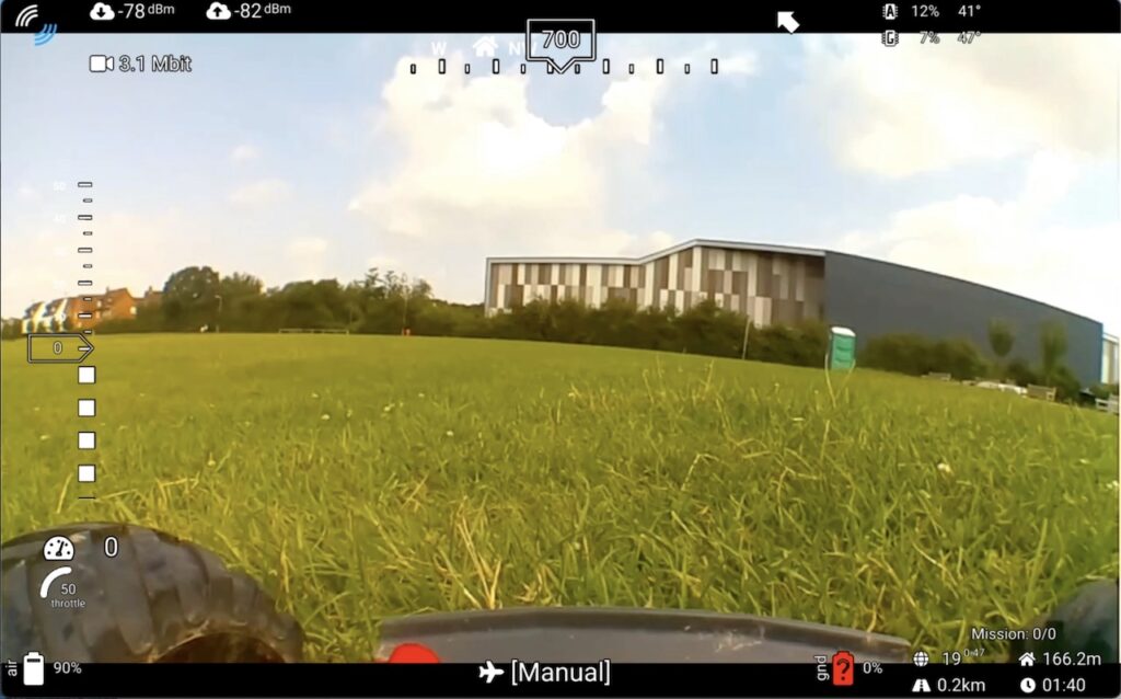
Whilst I have a few iNav things to sort out there, I’m pleased enough that the basic operation of Open.HD and my method of recording it is working pretty well. The ground vehicle was never intended to be any more than a test model to give me some confidence in the system before using it in a flying model. So in my next post I’ll be taking large (and pretty old) f450 quad frame and after testing iNav to make sure everything is ok in regular analog FPV I’ll be fitting this out with Open.HD and seeing what it can do.
Stay tuned for that!